In our increasingly connected world, every piece of information, every command, every beat of a digital heart often begins its journey as a carefully crafted signal. And at the core of shaping these invisible forces lies the powerful dual discipline of Waveform Generation & Modulation. It's the art and science of creating precise electrical or optical patterns and then encoding vital information onto them, making modern technology possible.
If you've ever listened to the radio, used Wi-Fi, seen an MRI, or even controlled a drone, you've witnessed the direct impact of these techniques. They allow us to translate complex data into a language that machines understand, transmit it across vast distances, and extract meaningful insights. Forget abstract theory for a moment; this is about equipping you with a practical understanding of how signals are born, shaped, and sent to do their jobs.
At a Glance: What You'll Discover
- The Foundation: Grasp the essential difference between generating a raw signal and modulating it with information.
- Common Waveforms: Learn the basic building blocks like sine, square, and triangular waves, and why each matters.
- Key Modulation Types: Understand how Amplitude, Frequency, Phase, and Pulse Width Modulation encode data.
- Tools of the Trade: Explore software, dedicated hardware like signal generators, and advanced solutions like the Moku Waveform Generator.
- Real-World Impact: See where these techniques drive innovation, from communication to advanced research.
- Practical Insights: Get actionable advice on selecting the right tools and avoiding common pitfalls in your projects.
The Heartbeat of Technology: Why Waveforms Matter So Much
Imagine a world without signals. No radio, no internet, no remote controls, not even traffic lights. Sounds like science fiction, right? Yet, that's precisely what we'd face if we couldn't reliably generate and manipulate waveforms.
At its simplest, a waveform is a graphical representation of how a signal's amplitude changes over time. Think of it as the "shape" of an electrical current or light wave. These shapes carry everything from a simple "on" or "off" command to complex data streams like high-definition video. The ability to craft these shapes (generation) and then imbue them with meaning (modulation) is fundamental to nearly every electronic system we interact with daily. From a tiny sensor reporting temperature to a massive radio telescope listening to distant galaxies, carefully engineered waveforms are the invisible threads holding our technological tapestry together.
Understanding the Building Blocks: What is Waveform Generation?
Waveform generation is precisely what it sounds like: the process of creating an electrical signal with specific characteristics. This could be a repeating pattern, a single pulse, or a complex, non-repeating sequence. These generated signals serve as the foundation upon which all further signal processing and communication depend.
Think of it like laying down a basic rhythmic track in music. You need a steady beat, perhaps a bassline, before you can add melodies or vocals. In electronics, these "rhythmic tracks" often take familiar shapes:
- Sine Wave: The most fundamental waveform, characterized by its smooth, periodic oscillation. It's the purest form of a single frequency signal and is crucial for understanding AC circuits, radio frequencies, and harmonic analysis.
- Square Wave: A signal that rapidly alternates between two distinct voltage levels. Ideal for digital logic (representing 0s and 1s), clock signals, and testing the transient response of circuits.
- Triangular Wave: Features a linear rise and fall between two voltage levels, creating a triangular shape. Often used in sweep generators, modulators, and as a test signal for amplifiers.
- Sawtooth Wave: Similar to a triangular wave but with a slow, linear rise and a sudden, sharp drop (or vice-versa). Commonly found in scanning circuits (like older TVs) and some musical synthesizers.
- Pulse Wave (or Rectangular Wave): A generalization of the square wave where the "on" time (pulse width) can be varied relative to the "off" time. Essential for digital communications, timing circuits, and power control (e.g., PWM).
- Noise Signals: Random fluctuations, often used to test system robustness or simulate real-world interference. White noise, pink noise, and Gaussian noise are common types.
- DC Signals: Not strictly a "wave" as it's a constant voltage or current, but it's a generated signal that acts as a baseline or power source in many circuits.
Beyond these fundamental shapes, engineers often need to generate much more intricate waveforms—custom patterns, complex data sequences, or signals that chirp (vary frequency over time). The tools and techniques for achieving this range from simple analog circuits to sophisticated digital signal processors. For a deeper dive into the devices that make this possible, you might want to explore a Complete guide to generator signals.
Shaping the Message: What is Waveform Modulation?
If waveform generation is about creating the signal, then modulation is about giving that signal a voice—encoding information onto it. Without modulation, our generated waveforms would be like a carrier pigeon flying with an empty satchel: useful for movement, but without purpose.
Modulation changes one or more properties of a carrier wave (typically a high-frequency sine wave) in response to a modulating signal (the information we want to send). This process allows a single carrier wave to transmit a variety of data, occupy a specific frequency band, and often travel long distances more effectively.
Imagine you're trying to communicate across a noisy room. You could shout, but that's just increasing the "amplitude" (volume) of your voice. What if you needed to send a secret message? You might vary the pitch of your voice (frequency) or the timing of your words (phase) to convey different meanings, even if your volume stays the same. That's the essence of modulation.
The primary ways to modulate a carrier wave involve altering its key parameters:
Amplitude Modulation (AM)
- How it works: The amplitude (strength or intensity) of the carrier wave is varied in proportion to the instantaneous amplitude of the modulating signal.
- Analogy: Changing the volume of your voice while keeping the pitch steady.
- Use Cases: Traditional AM radio broadcasts, certain types of data transmission. It's simple to implement but susceptible to noise.
Frequency Modulation (FM)
- How it works: The frequency (number of cycles per second) of the carrier wave is varied in proportion to the instantaneous amplitude of the modulating signal. The amplitude of the carrier remains constant.
- Analogy: Changing the pitch of your voice while maintaining a consistent volume.
- Use Cases: FM radio broadcasts (known for better sound quality and noise immunity than AM), walkie-talkies, data communication in modems.
Phase Modulation (PM)
- How it works: The phase (the position of a point in time on a waveform cycle) of the carrier wave is varied in proportion to the instantaneous amplitude of the modulating signal. Like FM, the amplitude remains constant.
- Analogy: Suddenly shifting the rhythm of a steady drum beat without changing its tempo or volume.
- Use Cases: Many digital communication systems (e.g., Wi-Fi, satellite communication), where abrupt phase shifts represent different data bits (e.g., BPSK, QPSK).
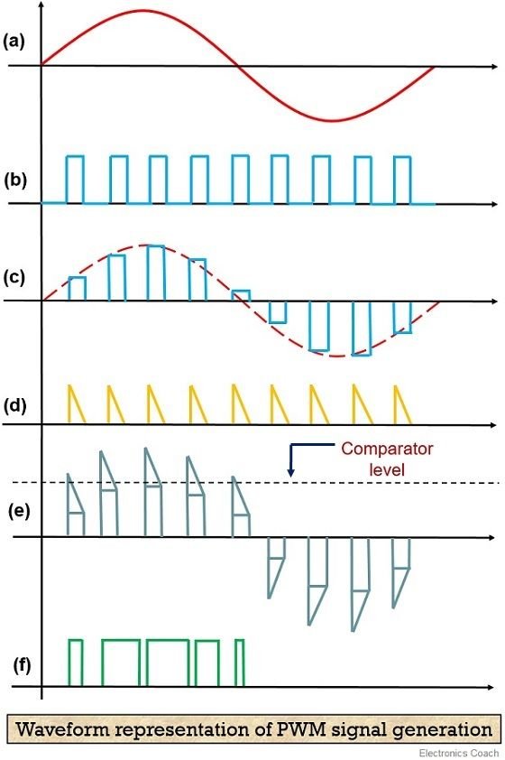
Pulse Width Modulation (PWM)
- How it works: This isn't strictly about modulating a continuous carrier wave, but rather modulating a series of pulses. The duration (width) of each pulse is varied to encode information or control the average power delivered to a load.
- Analogy: Adjusting how long a light switch is "on" within a brief period to control the effective brightness of a bulb.
- Use Cases: Motor speed control, LED dimming, power conversion, generating analog signals from digital sources.
By combining these basic modulation techniques, engineers create incredibly sophisticated communication systems, enabling everything from high-speed internet to complex scientific instruments.
The Toolkit for Creation: How Waveforms Are Generated and Modulated
Bringing waveforms to life requires a diverse set of tools, ranging from simple circuits to advanced software and dedicated hardware instruments. Understanding these methods is key to selecting the right approach for your application.
A. Digital vs. Analog Generation: A Fundamental Divide
At a high level, waveform generation can be broadly categorized into analog and digital methods:
- Analog Waveform Generation: Traditionally involved passive components (resistors, capacitors, inductors) and active components (op-amps, transistors) arranged in oscillators or function generators. These produce continuous, smooth waveforms directly. While still vital for specific applications, they can lack the precision, flexibility, and repeatability of digital methods.
- Digital Waveform Generation: Dominates modern practice due to its accuracy, stability, and programmability. Here, waveforms are first defined mathematically or sampled from real-world signals, converted into digital data, and then reconstructed as an analog signal. Key technologies include:
- Digital-to-Analog Converters (DACs): These are the core components that transform digital data (a series of numbers) into a corresponding analog voltage or current. The quality of the DAC directly impacts the fidelity of the generated waveform.
- Direct Digital Synthesis (DDS): A widely used technique that uses a phase accumulator, a lookup table (for waveform shape), and a DAC to generate highly stable, agile, and frequency-accurate sine waves, which can then be shaped into other waveforms.
B. Software & Programming Approaches: The Virtual Lab Bench
For many engineers and researchers, software offers unparalleled flexibility for designing, simulating, and generating waveforms.
- Mathematical Computing Software (e.g., MATLAB): Tools like MATLAB are incredibly powerful for defining and manipulating waveforms programmatically. MathWorks provides dedicated functions to generate common waveform types with high precision:
chirp: Generates linear, quadratic, or logarithmic chirps—signals whose frequency changes over time. Essential for radar, sonar, and spread spectrum communications.square: Creates square waves.rectpuls: Generates rectangular pulses of specified width.sawtooth: Produces sawtooth or triangular waves.
This programmatic approach allows for rapid prototyping, parameter sweeping, and the creation of highly customized or complex sequences not found in standard hardware.- Specialized Wireless Waveform Generators: For advanced wireless communication systems, the complexity of modulation schemes (like QAM, OFDM, MIMO) demands highly specialized tools. The Wireless Waveform Generator app within the Communications Toolbox for MATLAB/Simulink provides an intuitive interface to configure and generate waveforms compliant with various wireless standards (5G, LTE, WLAN) or custom schemes. This app simplifies the intricate process of creating baseband or RF signals for design, simulation, and testing of wireless systems.
C. Dedicated Hardware: Signal Generators & Arbitrary Waveform Generators (AWGs)
While software is excellent for design and simulation, generating high-quality, real-world signals for testing physical circuits or driving advanced systems often requires dedicated hardware.
- Function Generators: These are the workhorses of many labs, capable of producing standard waveforms (sine, square, triangle) across a range of frequencies and amplitudes. They are generally more affordable and simpler to operate for basic tasks.
- Arbitrary Waveform Generators (AWGs): The most flexible type of signal generator, AWGs can produce virtually any waveform shape that can be defined digitally. They work by storing a digital representation of the waveform in memory and then playing it back through a high-speed DAC. This makes them indispensable for simulating real-world signals, creating custom test patterns, or driving complex experiments.
Spotlight on Innovation: The Moku Waveform Generator
Take the Moku Waveform Generator by Liquid Instruments as a prime example of a state-of-the-art AWG built for demanding applications. This isn't just a basic signal source; it's a powerful, multi-channel instrument designed for precision and flexibility:
- Multi-Channel & Synchronization: It can generate up to six independent, phase-synchronized waveforms. This is critical for applications requiring precise timing and correlation between multiple signals, like driving multiple AOMs (Acousto-Optic Modulators) or EOMs (Electro-Optic Modulators) in optics experiments, or simulating complex multi-path radio signals.
- High Bandwidth: With a maximum bandwidth of 2 GHz, it can generate high-frequency signals crucial for RF system prototyping, fast circuit response evaluation, and advanced communications testing.
- Comprehensive Modulation: Beyond basic waveform generation, it excels at modulation. You can apply phase, frequency, amplitude, or pulse-width modulation not only to internally generated signals but also to external signals routed through the device. This "cross-channel modulation" capability is particularly powerful for simulating complex radio signals or creating intricate control schemes.
- Versatile Waveform Types: It supports a wide array of common waveform types, including modulated sine, square, ramp, pulse, noise, and DC. This broad versatility makes it suitable for diverse applications like radio signal simulation, evaluating the response of various circuits, and precise AOM driving.
- Advanced Triggering & Modes: It offers flexible triggering options via analog input, a dedicated TTL port, or even other output channels. This enables precise control over burst and sweep modes, essential for pulsed experiments, automated test sequences, or frequency response analysis.
- Integrated Workflow: The Moku Waveform Generator operates seamlessly within Liquid Instruments' Multi-Instrument Mode. This allows users to couple it with other virtual instruments like the Moku Spectrum Analyzer or Oscilloscope for real-time signal verification, offering lossless signal routing between instruments. This integrated environment streamlines the design-test-debug cycle.
- Automation-Ready: For researchers and engineers needing to automate complex experiments or production tests, it provides robust APIs for Python, MATLAB, and LabVIEW. This level of programmatic control is vital for accelerating development timelines and ensuring repeatability.
This type of instrument is engineered specifically for demanding applications such as: - AOM/EOM driving in quantum optics and laser systems.
- RF system prototyping and characterization.
- Precise signal stimulation in biological or physical experiments.
- System synchronization across multiple complex devices.
- High-speed system test and debug in R&D environments.
Mastering the Art of Modulation: Techniques and Applications
Modulation isn't just a theoretical concept; it's the engine driving countless real-world applications. Understanding the practical aspects of various modulation schemes reveals their power and limitations.
A. Amplitude Modulation (AM)
How it Works in Practice: In AM, a low-frequency information signal (like audio) varies the amplitude of a higher-frequency carrier wave. Imagine a radio station sending out a steady, high-pitched hum. When the announcer speaks, their voice causes that hum to get louder and softer, faithfully mimicking the speech's original volume changes.
Applications: While less common for high-fidelity audio today, AM remains prevalent in traditional radio broadcasts (especially shortwave and longwave due to their propagation characteristics), aircraft communications, and some digital data transmission where simplicity is prioritized over noise immunity.
B. Frequency Modulation (FM)
How it Works in Practice: With FM, the information signal changes the frequency of the carrier wave, while the carrier's amplitude stays constant. If our radio station announcer uses FM, their voice would cause the carrier's pitch to fluctuate up and down, but its loudness would remain steady.
Applications: FM is widely used for high-fidelity radio broadcasts (thanks to its superior noise immunity compared to AM), two-way radio systems (e.g., police, taxi, emergency services), and in some data modems where robust data transfer is crucial.
C. Phase Modulation (PM)
How it Works in Practice: PM alters the phase angle of the carrier wave in response to the information signal. Instead of varying amplitude or frequency, the waveform is subtly shifted forward or backward in its cycle. If the announcer were using PM, their words would cause slight, instantaneous shifts in the timing of the carrier wave's cycles.
Applications: PM is the foundation for many digital modulation schemes (e.g., PSK – Phase Shift Keying, QPSK – Quadrature Phase Shift Keying), which are ubiquitous in modern digital communications like Wi-Fi, cellular networks, satellite communications, and Bluetooth. It's highly efficient for encoding digital data bits.
D. Pulse Width Modulation (PWM)
How it Works in Practice: PWM generates a series of pulses. The key is that the width (duration) of each pulse is varied to represent the information or control signal. A wider pulse might mean "more power" or "higher value," while a narrower pulse means "less."
Applications: You'll find PWM everywhere:
- Motor Control: Precisely controls the speed and direction of DC motors.
- LED Dimming: Adjusts the brightness of LEDs by rapidly switching them on and off, varying the "on" time.
- Power Converters: Efficiently regulates voltage and current in power supplies.
- Digital-to-Analog Conversion: Creates an average analog voltage from a digital source.
E. Advanced Modulation Schemes (A Glimpse)
Beyond these foundational types, modern communication relies on sophisticated combinations and extensions:
- Quadrature Amplitude Modulation (QAM): Combines both AM and PM to encode multiple bits per symbol, significantly increasing data rates. Used extensively in Wi-Fi, cable modems, and digital television.
- Frequency Shift Keying (FSK): Represents digital data by shifting between discrete frequencies. Simple and robust, used in low-speed data links and RFID.
- Orthogonal Frequency-Division Multiplexing (OFDM): Divides a high-speed data stream into multiple slower data streams, each transmitted on a different frequency. This helps combat multi-path interference and is key to Wi-Fi, 4G, and 5G cellular.
These advanced techniques often require dedicated software tools, such as the MathWorks Wireless Waveform Generator app, to design and test, given their inherent complexity.
Practical Applications: Where Waveforms Drive Innovation
The principles of waveform generation and modulation are not confined to academic labs; they are integral to the functionality of countless devices and systems that touch every aspect of modern life.
A. Communications: Bridging Distances
This is perhaps the most obvious application. From the earliest telegraph to today's high-speed fiber optics, waveforms are the carriers of information:
- Radio and Television: AM and FM radio, digital terrestrial TV, satellite broadcasts.
- Cellular Networks (2G to 5G): Complex digital modulation schemes (QPSK, 16QAM, 64QAM, OFDM) are essential for voice and data transmission over vast geographical areas.
- Wireless Data (Wi-Fi, Bluetooth): Allows devices to communicate wirelessly over short distances, relying on intricate modulation for data integrity and speed.
- Fiber Optics: Light waves are modulated to carry immense amounts of data over glass fibers, forming the backbone of the internet.
B. Sensing & Measurement: Seeing the Unseen
Waveforms are crucial for probing environments and collecting data:
- Radar: Emits radio waves and analyzes the reflections to detect objects, measure distance, and velocity (e.g., weather radar, air traffic control, autonomous vehicles). Chirp waveforms are particularly effective here.
- Sonar: Uses sound waves in water for underwater mapping and object detection.
- Lidar: Employs laser pulses to create detailed 3D maps, critical for autonomous driving and geographical surveying.
- Medical Imaging (MRI, Ultrasound): Generates and receives specific waveforms to create detailed images of the body's internal structures.
C. Control Systems: Precision and Automation
In industrial and robotic applications, waveforms provide precise control:
- Motor Control: PWM is fundamental for efficiently controlling the speed and torque of electric motors in everything from electric vehicles to industrial robots.
- Power Electronics: Modulated waveforms manage power flow in converters, inverters, and power supplies, improving efficiency and stability.
- Robotics: Precisely timed and shaped pulses can control actuators and sensors for intricate movements.
D. Test & Measurement: Ensuring Reliability
Engineers rely heavily on generated waveforms to test the integrity and performance of electronic components and systems:
- Circuit Characterization: Injecting specific waveforms (sine, square, arbitrary) into circuits helps evaluate their frequency response, distortion, noise immunity, and transient behavior.
- System Debugging: Precisely controlled test signals can isolate faults and verify the correct operation of complex digital and analog systems.
- EMI/EMC Testing: Generating specific interference waveforms to test a device's susceptibility and emissions.
E. Physics & Research: Pushing the Boundaries
In advanced scientific research, custom waveforms are often at the forefront of discovery:
- Quantum Computing: Precisely shaped microwave pulses control the quantum states of qubits.
- Spectroscopy: Modulated light sources are used to analyze the interaction of light with matter, revealing its composition and properties.
- Optical Trapping & Manipulation: Modulating laser beams (e.g., using AOMs/EOMs driven by devices like the Moku Waveform Generator) can create intricate light fields to trap and move microscopic particles.
Choosing Your Weapon: Key Considerations for Waveform Tools
Selecting the right waveform generation and modulation tools for your project can feel daunting given the wide array of options. Here's a practical guide to help you make informed decisions:
1. Bandwidth/Frequency Range
- Why it matters: Determines the highest frequency signal you can generate or the speed at which your waveform can change.
- Consider: Are you working with audio frequencies (kHz), RF (MHz to GHz), or high-speed digital signals (multi-GHz)? Lower-cost function generators handle audio/low RF, while high-end AWGs and specialized RF signal generators push into multi-GHz ranges. (Remember the Moku Waveform Generator's 2 GHz bandwidth for RF applications).
2. Sampling Rate/Resolution
- Why it matters: For digital arbitrary waveform generators, the sampling rate defines how many data points per second are used to reconstruct the analog waveform. Higher sampling rates mean more accurate representation of complex or high-frequency waveforms. Resolution (e.g., 8-bit, 14-bit, 16-bit) determines the precision of each data point's amplitude.
- Consider: Do you need smooth, high-fidelity signals or can you tolerate some quantization noise? Higher resolution is crucial for low-noise applications and precise analog control.
3. Number of Channels
- Why it matters: How many independent or synchronized signals do you need to generate simultaneously?
- Consider: A single channel might suffice for basic testing. Multi-channel instruments (like the Moku Waveform Generator with its six synchronized channels) are essential for applications like phase-array antennas, multi-input/multi-output (MIMO) systems, or complex quantum experiments requiring multiple synchronized control signals.
4. Modulation Capabilities
- Why it matters: Can the instrument apply the specific types of modulation (AM, FM, PM, PWM, QAM) you need, and can it do so internally or with external modulating signals?
- Consider: Basic function generators might only offer simple AM/FM. Advanced RF signal generators and AWGs provide sophisticated internal modulators and often allow external modulation, offering greater flexibility (e.g., the Moku's cross-channel modulation).
5. Triggering and Synchronization Options
- Why it matters: How precisely can you start, stop, or burst your waveforms? How can you synchronize them with other instruments or events?
- Consider: Look for options like internal triggers, external trigger inputs (TTL, analog), gate modes, burst modes, and sweep modes. The Moku Waveform Generator's versatile triggering (analog, TTL, other channels) highlights its importance for automated or event-driven tasks.
6. Software Integration and APIs
- Why it matters: Can you control the instrument programmatically from software like MATLAB, Python, or LabVIEW? This is vital for automation, complex test sequences, and integrating into larger testbeds.
- Consider: Check for available drivers, software development kits (SDKs), and clear API documentation. Tools like the MathWorks Waveform Generator app are designed for seamless integration, and instruments like Moku actively promote their Python, MATLAB, and LabVIEW APIs.
7. Cost vs. Performance
- Why it matters: Your budget will always play a role. Higher performance (bandwidth, resolution, features) generally comes with a higher price tag.
- Consider: Carefully weigh your immediate and future needs. Sometimes, a software-defined approach combined with a versatile hardware platform (like Moku) can offer significant long-term value and adaptability compared to a rigid, single-purpose instrument. Don't overspend on capabilities you won't use, but also don't under-invest if your application demands precision.
Common Pitfalls to Avoid in Waveform Generation & Modulation
Even with the best tools, missteps can lead to inaccurate results or system failures. Being aware of these common pitfalls can save you significant time and frustration.
1. Aliasing
- The Trap: Occurs when a signal is sampled at a rate less than twice its highest frequency component (Nyquist frequency). The reconstructed signal appears as a lower-frequency component that wasn't present in the original.
- How to Avoid: Always ensure your sampling rate (for AWGs or digital generation) is at least twice, and ideally significantly higher than, the highest frequency you intend to generate or modulate. Use anti-aliasing filters on both the generation and acquisition side.
2. Jitter
- The Trap: Small, rapid variations in the timing of a waveform's edges or phase. It can lead to errors in digital systems or noise in analog signals.
- How to Avoid: Use high-quality clocks and oscillators. Minimize noise and interference in your power supplies and signal paths. For critical timing applications, choose instruments with specified low-jitter performance.
3. Incorrect Impedance Matching
- The Trap: When the output impedance of a signal source doesn't match the input impedance of the load, it causes reflections, signal loss, and distorted waveforms, especially at high frequencies.
- How to Avoid: Ensure all components in your signal path (generator, cables, attenuators, load) have matching characteristic impedances, typically 50 Ω or 75 Ω for RF, or high impedance for voltage measurements. Use terminators when necessary.
4. Overlooking Calibration
- The Trap: Instruments can drift over time due to temperature changes, aging components, or wear and tear. An uncalibrated instrument provides inaccurate readings or generates incorrect signals.
- How to Avoid: Regularly calibrate your waveform generators and modulation equipment according to the manufacturer's recommendations. For critical applications, verify outputs with a known, calibrated reference.
5. Excessive Noise
- The Trap: Unwanted electrical signals that interfere with your desired waveform, degrading signal quality and potentially masking important information.
- How to Avoid: Use shielded cables, proper grounding techniques, and maintain good power supply filtering. Keep sensitive components away from noisy environments (e.g., motors, power lines). Choose instruments with low noise floors.
6. Inadequate Output Power/Amplitude
- The Trap: The generated signal doesn't have enough power or amplitude to properly drive the subsequent circuit or component, leading to weak responses or non-functionality.
- How to Avoid: Check the output power requirements of your load and ensure your waveform generator can meet them. Use external amplifiers if necessary, but be mindful of introducing additional noise or distortion.
Your Next Steps in Waveform Mastery
Understanding Waveform Generation & Modulation isn't just about absorbing theory; it's about empowerment. You now have a clearer picture of how signals are born, shaped, and sent on their vital missions across virtually every technological domain.
Here's how you can continue your journey toward mastery:
- Get Hands-On: The best way to learn is by doing. If you have access to a function generator, oscilloscope, or even a microcontroller with PWM capabilities, start experimenting. Generate simple sine waves, then squares, then try to modulate them. Observe the results.
- Explore Software Tools: Dive into MATLAB's signal generation functions, or explore Python libraries for signal processing. Simulate complex waveforms and modulation schemes. The MathWorks Wireless Waveform Generator app is an excellent starting point for advanced communication scenarios.
- Investigate Specialized Hardware: If your applications demand precision, high frequency, or multi-channel synchronization, research dedicated instruments like Arbitrary Waveform Generators (AWGs). Look into innovative platforms like the Moku Waveform Generator to see how cutting-edge hardware addresses demanding scientific and engineering challenges.
- Connect the Dots to Your Field: Think about how waveform generation and modulation directly apply to your specific area of interest—be it embedded systems, RF design, biomedical engineering, or quantum physics. This direct relevance will deepen your understanding and spark new ideas.
- Stay Curious: The world of signal processing is constantly evolving. Keep an eye on new modulation techniques, faster hardware, and more intuitive software tools. The fundamental principles remain, but their application continues to innovate.
By embracing these principles and engaging with the tools available, you'll be well-equipped to design, analyze, and troubleshoot the intricate signals that power our modern world. The ability to create and manipulate these invisible forces is a truly indispensable skill, opening doors to innovation across countless fields.